


Blog
Why PCB Testing Is Necessary?
Testing is a crucial part of the manufacturing process for PCBs.
When PCB testing is conducted throughout the production cycle, it can help save money and prevent issues when it comes to the final production run.
Some design analysis techniques can be used during the early stages to help minimize major issues during the manufacturing process, but there’s also a wide range of PCB testing methods that can be used on physical boards. These tests, run on prototypes or small-scale assemblies, look most closely at potential shorts, solder joint issues and functionality, ensuring that each tested PCB will function as intended.
Benefits of PCB Testing
Many companies see PCB testing as an absolute must due to the many advantages it provides them. Check out some of the following top advantages of PCB testing:
● Bug identification: The primary benefit of PCB testing is that it helps identify problems in PCBs. Whether the issue lies in functionality, manufacturability or elsewhere, PCB tests identify issues in a PCB design and layout so that designers can adjust accordingly.
● Time savings: PCB testing in the early stages can help save time in the long run, allowing designers to identify major issues during the prototyping stage. Thorough testing enables designers to determine the root cause of each problem posed quickly and easily, making adjustments so that they can move on with production at a faster rate and reduce product lead-time.
● Cost reduction: PCB testing prevents wasteful production of faulty products by using prototypes and small-scale assemblies to test the products. By completing thorough testing early in the design process, designers can prevent wasteful full-scale assemblies of faulty PCBs, ensuring that the design is as flawless as possible before it goes into production. This step helps to significantly reduce production costs.
● Fewer returned products: When companies conduct PCB testing, they lower the chances of selling defective products or those that don’t meet performance standards. As a result, they don’t see as many returned products, leading to reduced costs associated with refunding customers and handling defective goods. Additionally, having fewer returned products can result in higher customer satisfaction and an improved company reputation.
● Increased safety: Since PCBs are often used in essential electronic technologies, their failure can cause major issues for a company’s productivity or an organization’s ability to perform essential services. A defective PCB could cause a fire, potentially putting those near it in danger. Testing prior to manufacturing can also ensure machines and workers aren’t damaged or injured due to an improper design during production.
While thorough testing isn’t necessary for all types of PCBs, especially matured products well into their product life cycle, the majority of new PCB designs need robust and frequent testing of the design process. By establishing an appropriate PCB testing procedure for your organization’s needs, you can experience the benefits of PCB testing.
WHAT IS PCB TESTING AND WHAT IS BEING TESTED?
PCB testing and inspection cover a wide variety of Printed Circuit Board Testing methods that check if a PCB meets standards. Some of these PCB standards revolve around ensuring the PCB functions properly according to a project’s specifications and that it doesn’t have any defects. Electric board testers and other Circuit Board Testing methods are used to conduct these inspections and PCB tests.
Circuit board testing procedures evaluate several components of PCBs. These components are analyzed in detail to ensure their quality. The primary components tested can be found below:
● Lamination: Lamination quality is essential to the lifespan of a PCB — peeling laminate can cause issues in the final functionality of a board. Generally, tests on lamination will look at the laminate’s resistance to peeling by force or application of heat.
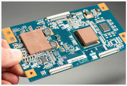
Copper plating: The copper foil on a PCB is laminated to the board to provide conductivity, but the quality of the copper is often tested, with tensile strength and elongation analyzed in detail.
● Solderability: Testing the solderability of a material is essential for a functioning PCB since it ensures that components can be attached firmly to the board and prevents soldering defects in the final product. The most commonly analyzed factor is wetting, which refers to how well a surface accepts liquid solder.
● Hole wall quality: Hole wall quality is another essential part of a PCB, ensuring that the hole walls will not crack or delaminate when the PCB goes into the field. Hole walls are generally analyzed in environments with cycling and quickly changing temperatures to see how well they react to thermal stress.
● Electrical: Electrical conductivity is essential for any PCB, so the ability of a PCB to pass electric currents with minimal leakage is a common test.
● Environment: Many PCBs operate in humid environments, so a common test for PCBs is for water absorption. In these types of tests, the PCB is weighed before and after being put in a humid environment, and any significant weight change results in a failing grade.
● Cleanliness: Cleanliness for PCBs is the ability to resist environmental factors like corrosion and humidity. Generally, these tests include analyzing PCBs before and after they’re put through varying environmental conditions.
Most of these factors are analyzed in early materials testing and environmental tests. However, factors like electrical conductivity and general functionality are analyzed with various methods and equipment.
TYPES OF PCB TESTING METHODS
PCB Testing Methods Guide
Several PCB testing methods are available, and no single one will catch every problem or meet the requirements of every designer. Each testing method should be considered closely to determine if it meets the specific needs of your manufacturing environment. Some factors to consider include the type of product you’re testing, the problems you’re testing for and the reliability of the test method. To give you an overview of the testing methods available, we’ve summarized the main qualities of four popular types of PCB testing methods below:
1. In-Circuit Test (ICT)
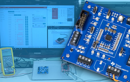
In-circuit testing is a popular PCB testing method that many PCB manufacturers prefer to employ, and it can find 98% of faults. This testing method uses special PCB testing steps and equipment, including:
● In-circuit tester: The tester system contains a matrix of hundreds or thousands of drivers and sensors, which perform the measurements for the test.
● Fixture: A fixture connects to the in-circuit tester and is the part that interacts directly with the board being tested. This fixture looks like a bed of nails and is designed specifically for the board in question. Each “nail,” or sensor point, connects to relevant points on the test board, feeding information back to the tester. Fixtures are generally the most expensive part of this system.
● Software: Software for the tester instructs the system on what tests to perform for each type of board being tested and dictates the parameters for a pass or fail.
Using the ICT method, a manufacturer can test individual components and measure their performance, regardless of the other components attached to them. Generally, this type of testing is best for 3analog circuits since it’s best at measuring resistance, capacitance and other analog measures. Additionally, the cost of the equipment means that this testing method is best suited for the final testing of stable, high-volume products, not for low-volume productions or early testing stages where the design may change multiple times.
2. Fixtureless In-Circuit Test (FICT)/Flying Probe Test
The fixtureless in-circuit test (FICT), also known as the flying probe test, is a type of ICT that operates without the custom fixtures, reducing the overall cost of the test. First introduced in 1986, FICT uses a simple fixture to hold the board while test pins move around and test relevant points on it using a software-controlled program. Since its introduction, FICT has gained widespread use throughout the electronics manufacturing industry for its versatility.
FICT testing is used for the same things as traditional ICT, but because of the way it goes about testing, it offers different advantages and disadvantages. While FICT is able to adapt to new boards quickly, easily and cost-effectively, with a simple programming change, it tends to be slower than the traditional ICT. This quality makes it an ideal testing method for small-production tests and prototype testing but less effective for large-scale production.
3. Functional Circuit Test
A functional circuit test is exactly what it sounds like — it tests the function of the circuit. This type of testing always comes at the end of the manufacturing plan, using a functional tester to check whether a finished PCB performs to specifications.
Some answers to common questions about functional circuit tests and how they work can be found below:
● How do functional testers work? Functional testers come in several types but generally share the same function — they simulate the final environment in which the PCB is supposed to function. Functional testers usually do so by interfacing with the PCB via its test-probe points or edge connectors and testing to certify that the PCB functions according to design specifications.
● Are functional circuits the same as ICTs? In some ways, functional circuit tests are similar to ICTs in that they use connectors to attach to the board. In the case of functional circuit testers, they use pogo pin devices to connect to the PCB and generally need fewer pins than an ICT fixture. The test equipment then runs programs to test the PCB, ensuring that the equipment functions exactly as intended.
● When do functional circuit tests occur? As previously stated, functional circuit tests are the last type of test to complete in a PCB Manufacturing plan, ensuring that the product going out functions according to specifications.
● What does a functional circuit test evaluate? Generally, functional circuit tests just look at the product’s functionality as a whole and grade it on a pass or fail basis. As a result, it’s not an ideal testing method for early prototypes since it doesn’t identify details about what’s wrong with the product.
4. Boundary Scan Testing
The boundary scan test looks at the wire lines on PCBs and is widely used as a way to test integrated circuits when it isn’t possible to reach all the nodes of the circuit. In this type of test, cells are placed in the leads from the silicon to the external pins, testing the functionality of the board.
The big differentiating quality of this type of test is its ability to assess a board without reaching all of its nodes. This quality is an important one for evaluating integrated circuits with multiple layers and high density since these types of PCBs have been becoming more common in recent years.
In fact, this testing method is quite versatile and able to be used for several applications, including system-level tests, memory testing, flash programming and central processing unit (CPU) emulation, among other functions. It’s commonly used in field service to detect problems in functioning systems.
HOW TO PROTECT YOUR PCB WITH BETTER DESIGNS
To better protect your PCB and have it pass an inspection and test, you may want to consider utilizing some of the top design techniques available today. Design for Manufacturing (DFM), Design for Assembly (DFA), Design for Test (DFT) and Design for Supply Chain (DFSC) are all some of the best design techniques used to ensure a PCB is manufactured correctly.
Essentially, designers use these techniques in the schematics and simulation stage to ensure a PCB meets various parameters and standards before it’s sent to the manufacturing stage. Learn more about DFM, DFA, DFSC and DFT below.
Related articles
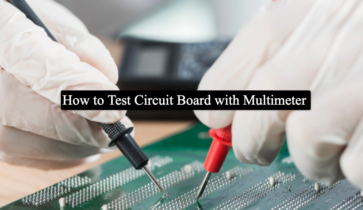
How do you test a PCB with a multimeter?
Multimeter and circuit boards are two things that go hand in hand. While the former is used for troubleshooting, circuit boards, on the other hand, are used in varied electrical equipment. One of the...
The difference between PCBA and PCB
PCB and PCBA are related terms in the field of electronics, but they refer to different things:1.PCB (Printed Circuit Board):A PCB, or Printed Circuit Board, is a flat board made of a non-conductive m...

what is as9100 certification?
When an OEM is sourcing out work -- let alone aerospace electronics manufacturing -- it’s likely to come across companies that boast about all sorts of certifications and capabilities.One certificatio...
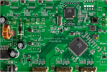
What electronic components are on the PCBA board
The specific electronic components present on a PCBA (Printed Circuit Board Assembly) can vary widely depending on the intended functionality and complexity of the electronic device being manufactured...
How can we test a pcb?7 pcb testing methods you need to know
When you order printed circuit boards (PCB), you know the pricey consequence of failure. The last thing you need financially is for your PCBs to suddenly drop dead -- or to have a shortened life span...
What is smt assembly?
As today’s electronics designs become smaller and more complex, more engineers are relying on surface mount technology. After the 1980s, this technology became the preferred PCB assembly technology in...
Leave a comment
